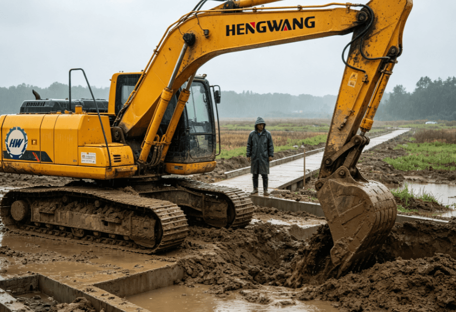
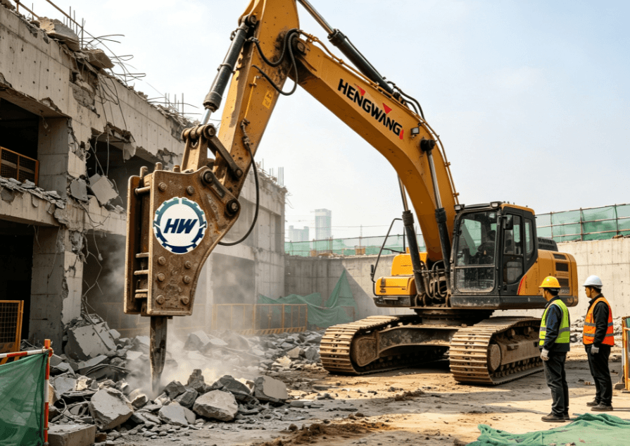
The main excavator parts are the undercarriage, upper structure, engine and hydraulic system, boom, arm, bucket or approved work tool, operator station and counterweight. Each part contributes to mobility, stability, control or the actual digging and handling function.
What the excavator parts decision should cover
The hydraulic system links the machine’s power source to its working components. An engine-powered pump pressurizes fluid, while valves, hoses, cylinders and motors convert that energy into controlled boom, arm, bucket, swing and travel movement [1]. The named parts and exact layout differ by manufacturer and configuration.
A useful way to read an excavator is to separate its travel base from its upper structure and then follow the working equipment outward from boom to arm to bucket. This helps an operator or buyer identify which component governs access, reach, digging, loading, attachment connection or routine inspection.
For every project, distinguish a general planning explanation from a model-specific conclusion. The current manufacturer specification, operating manual and approved configuration are the controlling sources for machine dimensions, operating weight, work range, hydraulic settings, attachments and operating limits. Site conditions, work method and local requirements must be checked separately; a general article cannot replace a competent project review.
Key factors to compare before work begins
The following table is a practical way to turn the excavator parts question into a documented selection or operating review. It is deliberately not a list of universal ratings. Complete it with the actual machine, working tool and job conditions, and retain the source documents used to make each decision.
| Decision area | What to identify | What to verify |
|---|---|---|
| Undercarriage | Tracks or wheels and travel components | Moves and supports the machine |
| Upper structure | Cab, engine, hydraulics and counterweight | Houses controls and rotates relative to the base |
| Front work equipment | Boom, arm, bucket or approved tool | Reaches, excavates, places or handles material |
| Hydraulic circuit | Pump, valves, lines, cylinders and motors | Transfers controlled fluid energy into motion |
Where a work tool is proposed, verify the mechanical interface, tool mass, auxiliary hydraulic requirements, hose routing, controls and any manufacturer restrictions. Hydraulic tools such as breakers, grapples, thumbs and screening tools may require a configuration-specific auxiliary circuit and a reliable connection; their availability in the market does not prove suitability for a particular machine [5].
How to turn the requirement into a safe equipment plan
First, describe the work rather than starting with a model name. Record the material to be moved, finished profile, depth or height, reach, loading position, access route, work duration, other machines, people and exclusion areas. This creates a measurable requirement that can be compared against current documentation.
Second, identify the proposed configuration. The configuration should include the undercarriage, boom and arm arrangement, bucket or approved attachment, optional hydraulic equipment and the specification document’s date. Comparisons are only meaningful when figures use the same configuration basis. Operating weight, for example, may be stated for a working machine with specified fluids and equipment, so it should not be compared casually with a shipping or bare-machine figure [3].
Third, confirm operating boundaries at the actual job geometry. Published work range is configuration-specific. If lifting is part of the work, use the matching current lift chart at the intended lift-point height and radius, and follow the project lifting plan. Capacity depends on configuration, load position, stability and hydraulic factors; it should never be inferred from category, bucket size or operating weight [4].
Fourth, document the information that remains unconfirmed. A planning record should identify the exact reference document, its revision or date, the assumed configuration, the required task outcome and the party responsible for confirmation. This is especially important when a proposal relies on an attachment, a non-standard boom or arm arrangement, a transport constraint, a finished surface, restricted access, an unfamiliar material or a lifting activity. Written confirmation prevents a general explanation from becoming an unsupported job instruction.
Fifth, organize the site around the planned work cycle. Mark the machine position, excavation or loading area, material placement zone, travel route, inspection area and pedestrian separation. Confirm overhead and underground constraints through the applicable project process. The operator should have a clear view or an agreed communication method for movements near people, trucks, structures or utilities. Stop work when the actual conditions differ from the documented assumptions and obtain the required review before continuing.
Finally, plan inspection and handover. Before a shift, use the manufacturer’s inspection procedure and verify that the intended work tool, pins or coupler, hydraulic connections, protective equipment and controls are in the approved condition. During the shift, record unusual performance, damage, leaks, excessive heat, unplanned idle time or changes in ground conditions. At handover, communicate the machine’s configuration, work completed, outstanding hazards and maintenance observations. These simple controls support reliable decisions without claiming any model-specific performance that has not been verified.
Keep the approval trail with the job records. It should show who checked the model and configuration, the current document used, the planned attachment or work tool, the work area, the site assumptions and the date of review. If the task, configuration, material, machine position, weather or ground condition changes, treat the earlier comparison as potentially outdated. Pause the affected activity and obtain the relevant technical or project review. This disciplined approach is particularly important where the machine will work near live services, finished structures, traffic, steep ground, people or suspended loads. It also supports clearer conversations with the supplier, owner, operator and maintenance team because they can distinguish a verified machine fact from an item that is still awaiting confirmation.
-2.png)
Operating and maintenance considerations
Operation should follow the current manufacturer manual, the site method statement and applicable local requirements. As U.S. regulatory context, OSHA construction requirements address matters such as earthmoving equipment controls, seat belts, braking, audible alarms and protective structures in applicable situations [2]. Requirements differ by jurisdiction and task, so the project team must verify the rules that apply to its work.
Hydraulic systems deserve disciplined inspection because they convert engine power into machine motion. In broad terms, an engine-driven pump pressurizes fluid, valves direct it through hoses, and cylinders and motors create controlled movement. Pressure is associated with available force, while flow affects the speed of movement; exact performance and controls vary by design [1]. Follow the approved process for leaks, damage, abnormal heat or unexpected motion.
Operating cost should also be evaluated with real job data. Fuel use is influenced by maintenance, air filtration, idling, work cycle, operator practice and machine-to-task matching. A forecast should therefore state its assumptions and distinguish measured data from estimates instead of presenting an unsupported hourly consumption figure [6].
FAQ: excavator parts
Is a bucket part of the excavator or an attachment?
A bucket is commonly the standard work tool, but its size and configuration can vary. Confirm the supplied configuration and approved alternatives in the current documentation.
Why is the counterweight important?
It contributes to the machine’s configured balance. It is not a substitute for the manufacturer lift chart, ground assessment or task-specific operating limits.
Can components be interchanged freely?
No. Pins, couplers, hydraulic requirements, load effects and guarding vary. Any proposed fitment requires manufacturer or supplier confirmation [5].
Scope note and next step
This guide provides a selection and planning framework, not machine-specific operating approval. Confirm current specifications, work range, lifting information, attachment fitment, fuel use, site conditions and legal obligations with the manufacturer, qualified supplier and project team before work begins. For a starting point when reviewing product categories, see the HengWang excavator range and request the current documents for any machine under consideration.
References
- [1] Volvo CE — Understanding Excavator Hydraulic Systems.
- [2] U.S. OSHA — 29 CFR 1926.602, Material Handling Equipment.
- [3] Milton Rents — Excavator Rental Guide: 5 Specs That Matter for Your Job.
- [4] Caterpillar — Finding Your Excavator Lift Capacity.
- [5] Stucchi USA — Excavator Attachments and Auxiliary Hydraulics.
- [6] Carolina Cat — Construction Equipment Fuel Management Guide.